
Eluminate AHF 400 / 480 V
Reliable operation starts with better power quality
Harmonic currents can contribute to additional heat, energy losses and operational disruptions. Eluminate AHF reduces harmonic currents and the resulting strain on the electrical system.
Lower energy losses and heat generation Can reduce energy losses and heat generation in cables and transformers.
More reliable operation Can reduce operational disruptions associated with harmonic currents.
Reduced strain on electrical equipment Can reduce electrical and thermal strain on equipment.
When harmonic currents become an operational problem
Harmonic currents increase energy losses and heat in cables and transformers, putting strain on the electrical system and increasing electricity costs.
An example: a pump controlled by a variable frequency drive
The variable frequency drive controls the pump speed but is also a non-linear load that can draw harmonic currents from the supply. This can increase losses and heat in cables and transformers.
The problem
Controls the motor speed
How Eluminate AHF helps
Eluminate AHF injects compensation current at the connection point, reducing the harmonic content of the supply current.
Increased losses and heat
Harmonic currents increase energy losses and heat in cables and transformers, putting strain on the electrical system and increasing electricity costs.
Operational disruptions and production stops
Harmonic distortion causes operational disruptions, unwanted trips and problems with sensitive equipment. The consequences are unnecessary production stops and additional troubleshooting.
Power quality requirements
Power quality and grid connection requirements may require harmonic currents to be reduced. We help establish the requirements, size the solution and document the result.
Relevant for variable frequency drives, UPS systems, battery energy storage systems (BESS), solar inverters and EV charging equipment – for example in process industries, water treatment facilities and data centres.
Compensation that follows the load
Compare the current waveform before and after compensation. Eluminate AHF supplies a compensation current that counteracts the harmonic currents. The result is a supply current with lower harmonic distortion.
Compare the current waveform with and without AHF.
THDi indicates the level of harmonic distortion in the current. A lower value means less harmonic distortion.
Simulation of a balanced three-phase variable frequency drive with a six-pulse rectifier. The values illustrate the principle; results in your installation depend on load and sizing.
- 1Measurement
Current is measured continuously.
- 2Analyse
The filter identifies harmonic components and calculates the required compensation.
- 3Compensate
The filter supplies compensation current that counteracts the harmonic currents.
- 4Adapt
The filter continuously adjusts the compensation as the load changes.
Measurement and connection
The filter is connected in parallel with the electrical system. Current is measured using current transformers (CTs), which can be installed on either the supply side or the load side of the AHF connection point. The diagrams show the two measurement principles.
Measures the supply current after compensation and provides feedback to the AHF control.
Measures the load current that the AHF needs to compensate.
Load current + AHF compensation current = supply current with reduced harmonic content. + marks the connection point. The CT location determines which current the filter measures and uses for control.
Effective compensation. Lower energy losses. Scalable capacity.
Indicates how effectively the filter reduces the selected harmonic currents. Performance in the actual installation is verified after commissioning.
High efficiency means lower internal energy losses and less heat generated in the filter.
More modules can be combined as needed. Their number and rated current are selected from measurements and installation data.
Technical information and datasheet
Follows the load
The filter continuously adjusts compensation as the load changes.
Mounting
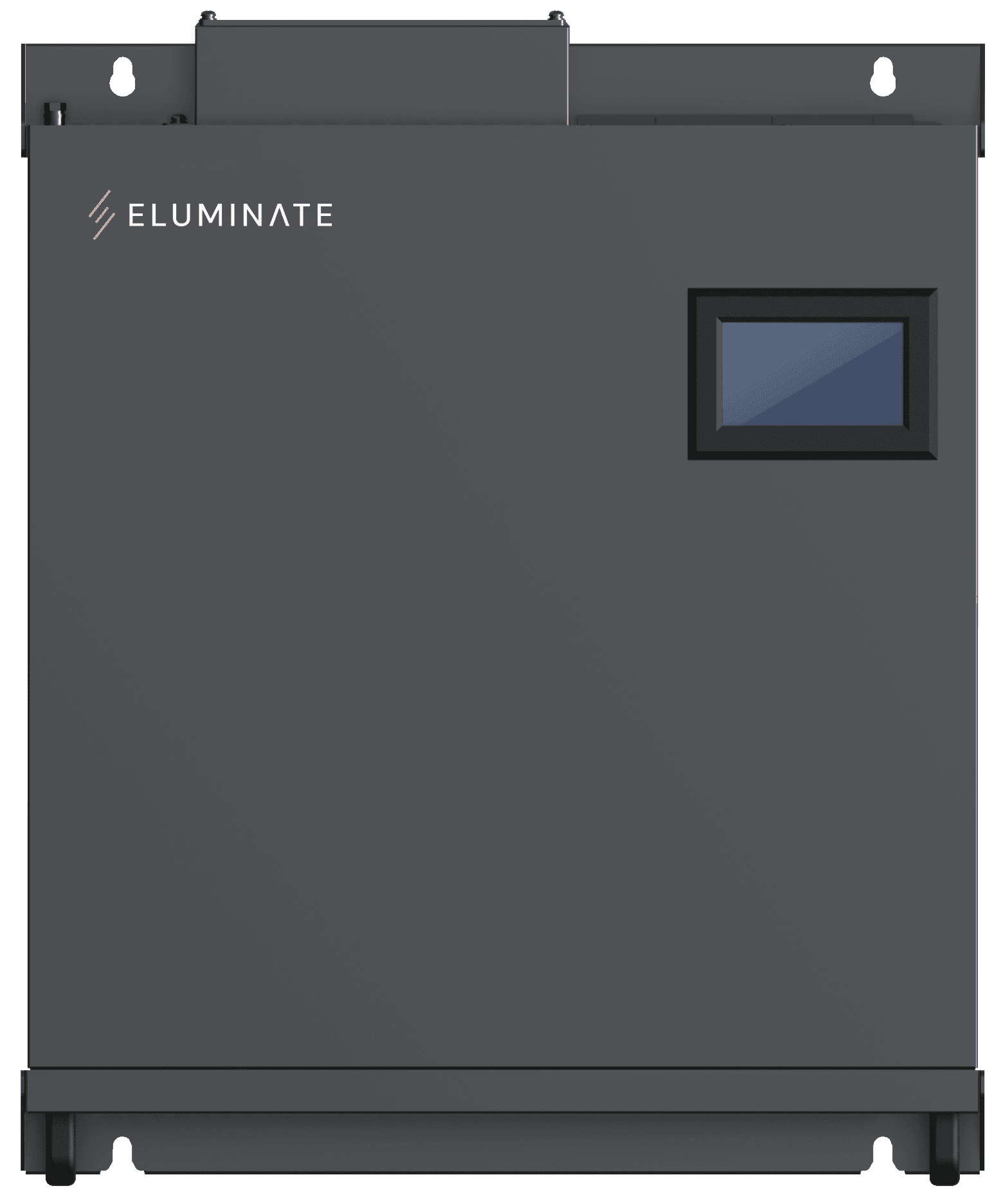
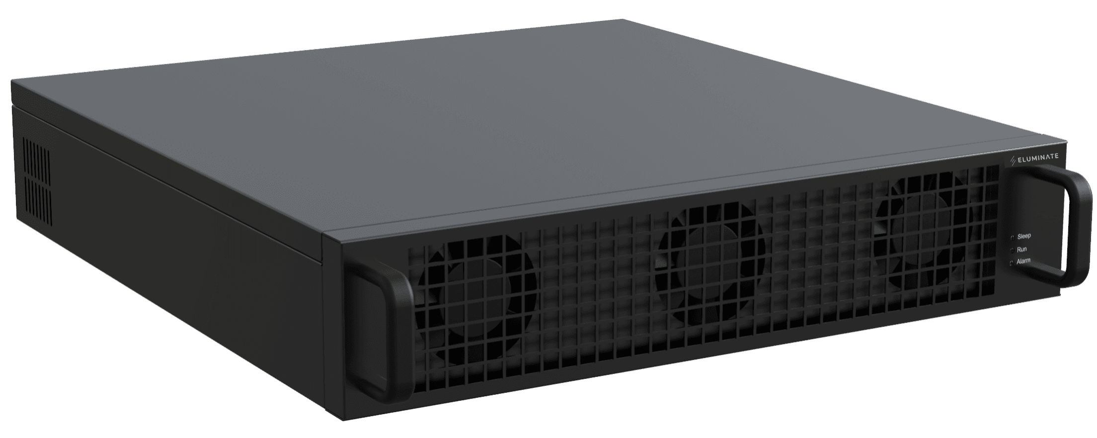
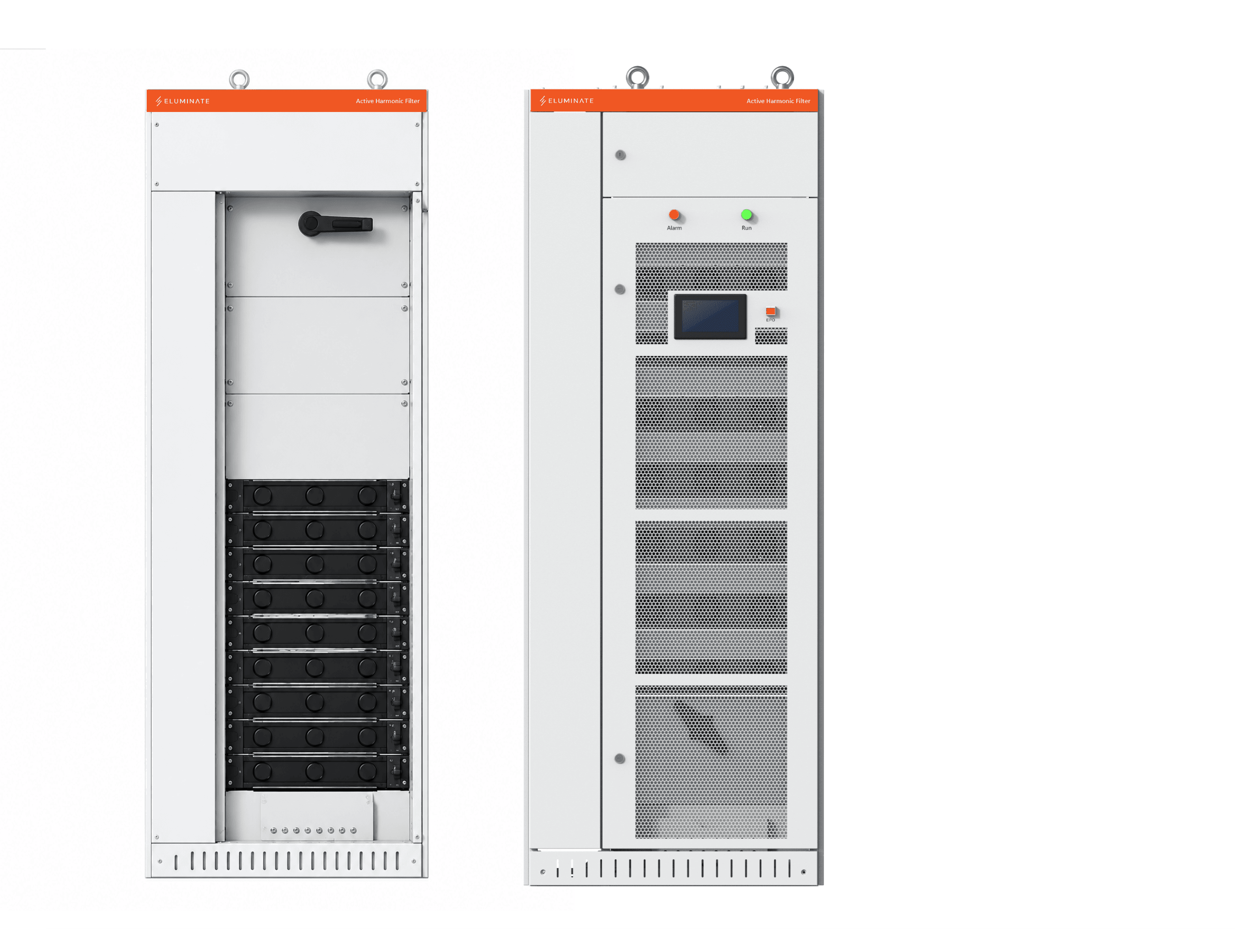
A wall module, rack module in your own cabinet or complete cabinet solution is selected to suit your installation and available space.
Technical values depend on rated current and configuration. The separate datasheet contains the details; Eluminate confirms the solution for your electrical system.
Download datasheet (PDF)Wall, rack or cabinet – tailored to the installation
Eluminate AHF is available as a wall-mounted module, a rack-mounted module for your own cabinet or a complete cabinet solution. The choice depends on the installation, available space and required level of protection.
Select the system voltage and enter the required compensation current. The calculator provides a preliminary module selection based on the available Eluminate AHF modules.
Cabinet solutions can include a central 7” control screen (HMI). Protection class is selected for the project, with options such as IP54 or IP55. The modules are rated IP20.
What does higher efficiency mean for energy costs?
Compare the filter's own energy losses and adjust electricity price and annual load to suit your operation.
Equivalent full-load hours convert varying annual load into the corresponding number of hours at full compensation current.
Calculation example: 150 A · 400 V · 99 % / 97 % efficiency.
4,000 equivalent full-load hours.
per year with your selected electricity price and load
Annual saving from lower energy losses in the filter
The calculation compares the filter's own energy losses using the module datasheet convention: voltage × compensation current × loss fraction. The reference filter is a calculation example. Actual savings depend on load, operating hours, configuration and electricity price.
From measurement to a documented solution
We start with the problem you are experiencing. We then measure the electrical system, size the solution and document the result.
- 01
Measurement
We identify the issue and measure the electrical system under relevant operating conditions, so the solution is based on actual data.
- 02
Sizing
We size the required filter capacity, select the appropriate configuration and plan installation and commissioning.
- 03
Verification
We measure the result at the agreed point and document the solution.
Installation and documentation
Information for the technical assessment
- Single-line diagram
- System voltage and electrical system configuration
- Load list and load profile
- Power quality measurement and harmonic spectrum
- Power quality and grid connection requirements
- Ambient conditions: temperature, altitude and enclosure
Measurement point and capacity
The measurement point and required filter capacity are determined based on the electrical system, load conditions and the issue to be addressed. Current transformer locations and measurement points are confirmed during the technical assessment.
Installation and operation
The solution is tailored to available space, environmental conditions and the required protection class. Eluminate supports installation and commissioning.
Documentation and support
The selected solution is supplied with the relevant technical documentation. Eluminate can support installation, commissioning, verification and ongoing service.
Bring harmonic currents under control
Tell us what you are experiencing in your electrical system. Together, we assess the issue and identify the right solution. We support the entire process: measurement and analysis, product selection, installation and verification of the result.
Download the brochure as PDF
Technical information and datasheet
Technical data in one datasheet
This brochure provides an overview of the solution. Detailed product data for Eluminate AHF is available in the datasheet for the next stage of the project.
- Control and compensation
- Communication and monitoring
- Protection and robustness
- Mechanics and system integration
- Module sizes and configurations